
Many years ago, a Silicon Valley startup built a juice machine that required an app download and a Wi-Fi connection to work. This overkill juicer quickly became viral for posing the question:
Why would you build an overly complicated product if a more functional design could fulfill the same application?
Regardless of the product you’re building, it should retain the necessary design complexity to fulfill its intended application. The goal of the Design for Manufacturing process is to help your product accomplish its purpose in its simplest form.
Many custom manufacturers rush to provide quotes without proper design evaluation, leading to parts that are either overly complex or inadequately engineered. Both options result in unpredictable pricing and quality problems. Strouse takes a different approach: our engineers thoroughly evaluate each product from the start to ensure it’s only as complex as its goals require.
Today, we will help you understand DFM, its effects, and how to improve your technical drawings for the best results.
What is Design for Manufacturability?
Design for Manufacturability (DfM) ensures that a product's design can fulfill its intended purpose without overcomplications. This is done by aligning design specifications, tolerances, and materials with the part’s application and process.
HOW DOES IT COMPARE TO DFA?
Design For Assembly (DfA) holds principles similar to those of DFM. In production engineering, it refines product assembly by:
- Minimizing the number of parts
- Modifying the part geometry
- Improving handling

Companies use Design for Manufacture and Assembly (DfMA) to create optimized manufacturing and assembly processes that align with the solution's needs.
How Does DfM Affect Custom Product Manufacturing?
The DfM process evaluates manufacturing complexity and identifies necessary design adjustments to ensure a product can be efficiently produced while meeting its intended specifications.
Depending on the design and its purpose, DfM could ultimately result in either a simpler or more complex process. Either way, the most effective product will accomplish the application in its simplest form. Overly sophisticated designs result in expensive machine processes and strict quality requirements, which add up considerably during mass production.
For example, a client once approached Strouse with a 7-layer design with each layer heavily toleranced. After a discussion with our client, we realized that not only would it cost a fortune to build, but that the design was far more complex than it needed to be. In response, our engineers combined layers to transform the overdesigned part into a 5-layer design that specified the most critical functional tolerances.
“If you can create a very simple widget to solve a problem, or a very complex widget to solve the same problem, you’ll choose the simple option every time.” —Scott Chambers, Strouse VP of Sales & Marketing
Conversely, some product designs appear deceivingly simple when, in reality, they require a far more challenging manufacturing process than anticipated. For instance, certain processes (like hand laminations) don’t always translate easily on a large scale and might complicate the process more than anticipated. Even simple designs can become complicated depending on the material—even more so when you have unnecessarily tight tolerances. Watch out, sometimes it’s the easy ones that’ll get you!
Communicating your part’s functional needs during an initial product evaluation with a custom manufacturer or converter is the best way to navigate a discussion on design manufacturability.
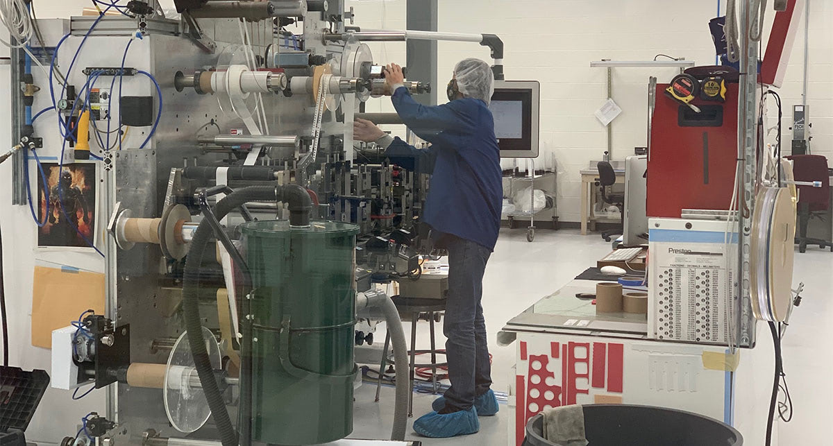
How To Improve Your DfM in Converting
As flexible material converters, we’ve spent years making design changes to prevent future headaches. If you know your product is going to need converting capabilities (or you just really love reading about converting), here are some tips on achieving better results.
1. GET INVOLVED WITH A CONVERTER EARLYChatting with a converter about your design is like bringing your baby to the hair salon: if you go before the baby has hair (i.e., before you have a technical drawing), there isn’t much we can do for you. However, if you wait until they’re a teenager to cut it, the unruly hair will cause far more trouble than it would’ve if you had managed it sooner. The best time to approach a converter is after you have a design draft that you are ready to start prototyping.
2. SIMPLIFY YOUR DESIGN
While this may seem like an obvious answer, there are many ways to reduce product complexity to aid a design's manufacturability.
 Design simplification methods include:
- Combining & reducing layers
- Simplifying print design (fewer colors, larger text, etc.)
- Eliminating unnecessary features
- Loosening tolerances (especially tight corners)
And regarding that last point, tight tolerances are the number one factor affecting die cut design complexity.
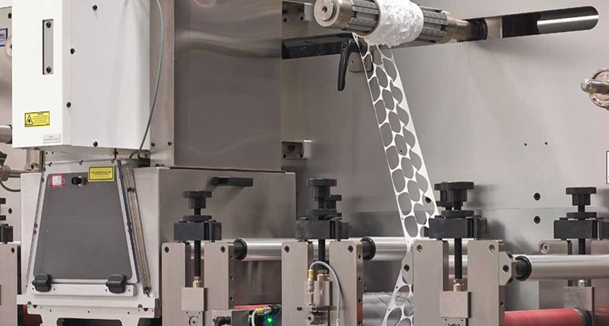
3. AVOID OVERLY TIGHT TOLERANCES
Realistic die cut tolerances are necessary for a functional design.
Overly tight tolerances, potentially carried over from CNC machining as “default title block tolerances,” will drive up your costs and unnecessarily complicate the production process. As a rule of thumb, loosen your tolerances as much as the design allows.
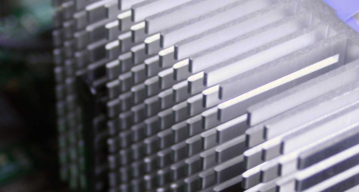
BEWARE OF MULTI-LAYER STACK-UP TOLERANCES
Multi-layer material stack-ups require careful attention to ensure that the necessary elements remain aligned. It’s easier to specify the relationship between elements rather than tolerancing every measurement on individual layers.
4. OFFER YOUR TOLERANCES IN COORDINATE SYSTEMS
Two ways to indicate tolerances in a technical drawing are GD&T (Geometric Dimensioning & Tolerancing) and Coordinate Tolerancing.

a. WHAT IS GD&T?
GD&T (Geometric Dimensioning & Tolerancing) drawings contain a box of symbols identifying different types of tolerances, such as angularity and concentricity.
Although GD&T makes the most sense for 3D manufacturing, machining, or molding, it isn’t the best measurement for converted parts. The circular tolerance zone makes it more challenging to define the required press adjustments and verify whether die cut parts consistently meet GD&T specifications.
Strouse can build parts using GD&T, but we often translate GD&T to coordinate tolerancing for our processes, measurements, and adjustments. Unfortunately, these adjustments may result in tighter tolerances (and higher prices) than you need (or looser measurements that affect the part’s shape). After multiple design revisions with different companies, some drawings might even pick up conflicting basic dimensions alongside their GD&T.
To avoid GD&T issues, clarify what you need to get out of your drawing and which dimensions are critical to your process. If your design is especially complex, then we will contact you to discuss tolerances and ensure everything lines up perfectly.
Strouse emphasizes having meaningful conversations about your functional tolerances to determine their variability, given the scope of our processes.
b. WHAT ARE COORDINATE SYSTEMS?
Coordinate tolerancing, or “plus/minus tolerancing,” involves calling out individual dimensions' upper and lower limits. Coordinate tolerances are generally the easiest for material converters to follow because the tolerance zone is more easily defined and translates better into the converting process.
For example, converters calibrate machine-web and cross-web direction measurements on the axis that aligns with coordinate-dimensional targets, which lends itself to making press adjustments. Defining your coordinate tolerances in advance will help speed up the converting and inspection processes.
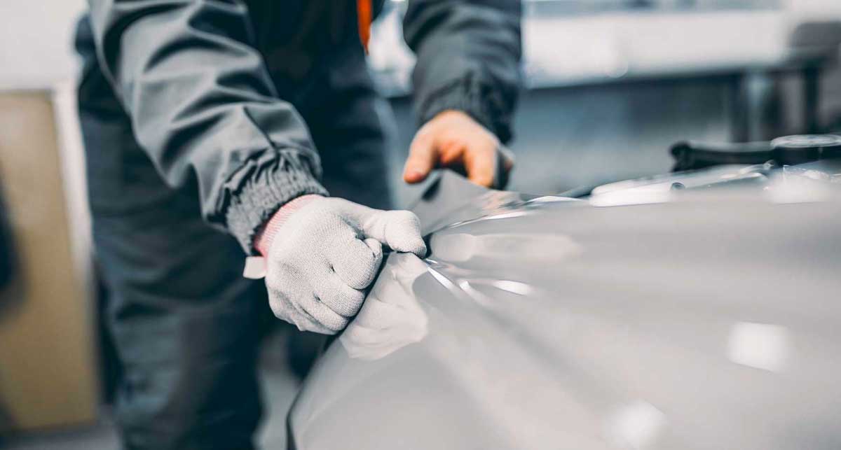
5. CHOOSE CONVERTING-FRIENDLY MATERIALS
Some materials are more challenging to convert than others, which may affect their cost, the price of tooling, and the difficulty of holding your tolerances.
For example, thick materials like foam and rubber or sheeted materials are more difficult to convert in bulk. Substrates with low surface energy may require specialized adhesives or treatments.
In any case, discussing materials with a converter can help ensure that your design uses the most suitable production materials.
Design Prototyping and Testing with a Converter
Sketching your design is an essential first step of the process; however, the only way to know whether you have a functional product for certain is through application testing.
As a flexible material converter, Strouse builds accurate part prototypes to help you test your design and materials. Using our engineering expertise, we will help optimize your part design for manufacturing and lay the foundations for the path leading to full-scale production.

Contact us today to improve your design’s manufacturability and begin rapid prototyping.
The sooner you begin discussing your part with a manufacturer or converter, the less time and money you’ll spend on design features that aren’t practical or feasible for your process.
If you have any questions about design efficiency or converting, please contact us or look for answers in our Learning Center.